Observer Cameras and Local Tetrads
Scrollable formula. Use Left and Right arrow keys to reveal hidden content.
Scrollable table. Use Left and Right arrow keys to reveal additional columns.
Scrollable figure. Use Left and Right arrow keys to inspect hidden content.
A relativistic camera is a local physical measurement model, not a coordinate rectangle placed near a black hole. It specifies an observer four-velocity, an oriented orthonormal tetrad, a screen projection, frequencies, and pixel sampling. Only after these choices are converted into null coordinate momenta can a ray integrator begin. Making that conversion explicit prevents coordinate axes and image conventions from masquerading as observables.
Required background. Affine and Variational Geodesics supplies null momenta, affine freedom, and observer contractions.
Helpful background. Formulations of General Relativity supplies frames and numerical metric data; Differential Equations for Relativity supplies ray integration; Black-Hole Astrophysics supplies source and viewing configurations; and Computational Relativity supplies the shared numerical-evidence framework.
A camera is an oriented tetrad
Section titled “A camera is an oriented tetrad”Let the camera observer have future-directed four-velocity with . Choose
The spatial leg points from the camera toward the scene and defines the optical axis, while and define horizontal and vertical screen directions. State the orientation by requiring the ordered tetrad to agree with the spacetime volume form. Swapping the screen legs or reversing one flips image handedness even though every leg remains normalized.
For a pinhole camera, a pixel determines a unit direction toward the scene. The arriving future-directed photon travels in the opposite spatial direction, . This construction assumes geometric optics and a camera small enough that one local tetrad describes each ray launch; an extended detector requires a tetrad field and an explicit aperture model. Use cyclic frequency and a frequency-normalized null tangent , so the physical photon momentum is in the inherited units. Its local components are
and coordinate momentum
This state is null by construction. To trace toward the emission event, retain the future-directed momentum and integrate with decreasing affine parameter; do not silently negate only selected components. Vincent and collaborators make the observer-to-ray construction operational in Vincent et al. 2011, §§2.1.1–2.1.2, Eqs. (1)–(8), and Appendix A.
Pixel maps and redshift
Section titled “Pixel maps and redshift”For screen coordinates and focal distance , all in the same length unit, use the virtual screen in front of the camera:
Then and . Decreasing moves toward the scene and into the past simultaneously. At the central pixel, and the future photon arrives along .
The two arrows in the figure distinguish a sky direction from a photon’s arrival direction. All screen quantities live in the same local rest frame before the tetrad converts them into coordinate components.
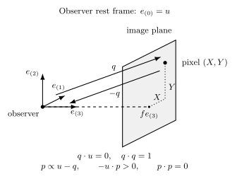
Local observer-frame construction for a virtual pinhole screen centered at . The pixel selects , while the arriving future-directed tangent is with positive measured frequency. Backward tracing follows decreasing affine parameter toward the scene. Perspective is schematic and not to scale; this is not a picture of a bent spacetime geodesic or a physical lens.
The solid-angle element is
Only near the axis does this become . Equal areas on a wide planar screen therefore do not subtend equal solid angles; summing specific intensities without these weights biases the total flux.
The screen model determines . A small-angle planar camera, a true angular or fisheye map, and an impact-parameter screen are different projections away from the optical axis. Record field of view, pixel-center convention, aspect ratio, and whether increasing horizontal coordinate points along or its negative. Pixel edges rather than centers matter when integrating flux.
Frequency transport is encoded by observer contractions. For emitter and camera velocities and ,
This scalar combines gravitational and kinematic shifts; splitting it into named pieces is generally coordinate or model dependent. Check the sign and normalization at the camera, then repeat at emission. A negative measured frequency signals a time-orientation error.
For a simple redshift check, take static emitter and camera outside a Schwarzschild horizon, at radii and . Their measured frequencies are , so
An emitter at seen from infinity has : its photons are redshifted. This static test contains no orbital Doppler effect.
At finite camera radius, the observer is not automatically “at rest at infinity.” Specify whether it is static, orbiting, freely falling, or normal to the numerical slice. In an ergoregion a static observer may not exist. Camera radius refinement tests the approximation of an asymptotic observer, but moving the camera also changes angular scale unless the screen is recalibrated.
Calibration and benchmark suite
Section titled “Calibration and benchmark suite”The page uses a versioned synthetic benchmark suite rather than observed images. Pin its metric definitions, camera configurations, checksums, and exact ray-tracing software revision. The evidence cutoff is 2026-08-18. Any later comparison with an Event Horizon Telescope product must identify the official data release and calibration version separately; no instrument likelihood is used here.
Calibration begins with tetrad Gram-matrix residuals, orientation, camera scale, frequency units, and the null residual of every initialized pixel. In flat spacetime, a regular angular grid must reproduce the intended straight-ray directions and solid angles. In Schwarzschild or Kerr, compare geodesic endpoints and conserved quantities with analytic first-integral calculations. Rotate the spatial tetrad by a known transformation: the image should rotate or remap predictably, while scalar frequency shifts and integrated flux remain consistent after accounting for pixel solid angle.
Repeat the same physical camera in a second coordinate chart. Coordinate components of the tetrad and momentum will change, but local components, redshifts, and mapped emission events should agree. Gold and collaborators show why camera placement and setup are major comparison variables in Gold et al. 2020, §§3.1, 5.1, and 6.
Selections, metrics, and systematics
Section titled “Selections, metrics, and systematics”Selections fix observer worldline, camera time, radius, inclination, frequency band, field of view, pixel mask, projection, and ray termination rules before viewing the result. Comparison metrics include the maximum tetrad Gram residual, null residual distribution, endpoint separation, pixel-direction angular error, redshift difference, and image norm after a declared geometric remapping. These are deterministic residuals; without observed data there is no likelihood or prior.
Systematic variations should include coordinate chart, tetrad construction, screen rotation, projection, camera radius, pixel resolution, and ray tolerance. Treat image translation or rotation as calibration only when predicted by the declared basis transformation; optimizing alignment after seeing the image can hide a handedness error.
The environment record pins the metric input and checksum, tetrad and projection algorithms, interpolation, precision, harmonic or image libraries, and software revision. A clean reproduction regenerates camera states, emits every tetrad and initial momentum, integrates the benchmark rays, and reports refinement and coordinate-transform comparisons. The dominant failure mode is a normalized but skewed or oppositely handed screen basis. Reject the result if orthonormality or null residuals fail, frequencies change sign, invariant endpoints depend on chart, or image orientation cannot be predicted from the recorded tetrad.
Check your understanding
Section titled “Check your understanding”A camera code normalizes three coordinate basis vectors independently and uses them as screen and optical axes. Each has unit norm, but their pairwise inner products are . The programmer proposes multiplying each initialized four-vector by one nonzero scalar to enforce . Can this repair the camera?
Solution
No. Unit length does not imply orthogonality. Moreover, , so a nonzero scalar cannot turn a non-null vector into a null one. Adjusting its temporal component instead could impose nullness, but would still leave the wrong pixel direction. Construct a genuine orthonormal tetrad, verify its handedness and Gram matrix, then regenerate the pixel directions. Compare the corrected camera under a coordinate change and known screen rotation. The original images carry a direction-dependent shear that could be mistaken for lensing.
Continue with Numerical Covariant Radiative Transfer.
References
Section titled “References”- Gold, Roman, et al. 2020. “Verification of Radiative Transfer Schemes for the Event Horizon Telescope.” The Astrophysical Journal 897, 148. DOI.
- Vincent, Frédéric H., Thibaut Paumard, Éric Gourgoulhon, and Guy Perrin. 2011. “GYOTO: A New General Relativistic Ray-Tracing Code.” Classical and Quantum Gravity 28, 225011. arXiv.